
3D geometries are made up of different elements known as components. The three different components are Faces, Edges and Vertices.
To begin selecting, you first need to pick a component mode. This can be done from the user interface, or the keyboard shortcuts below. Selecting components works much like selecting regular objects. We can click on a component to select it, Ctrl + click to add to the current selection, and Alt + click to remove from the current selection. Just as with selecting objects, we can create selection boxes by clicking and dragging.
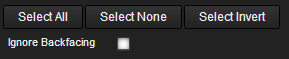
The current selection can be inverted by clicking on the Select Invert button, or from menu under File > Edit > Select Invert.
| Icon | Name | Description | Shortcut |
|---|---|---|---|
| Select | Select objects without transforming | Q | |
| Move | Select and Move objects | W | |
| Rotate | Select and Rotate objects | E | |
| Scale | Select and Scale objects | R | |
| Object | Select entire object | T | |
| Face | Select faces of an object | Y | |
| Edge | Select edges of an object | U | |
| Vertex | Select vertices of an object | I |
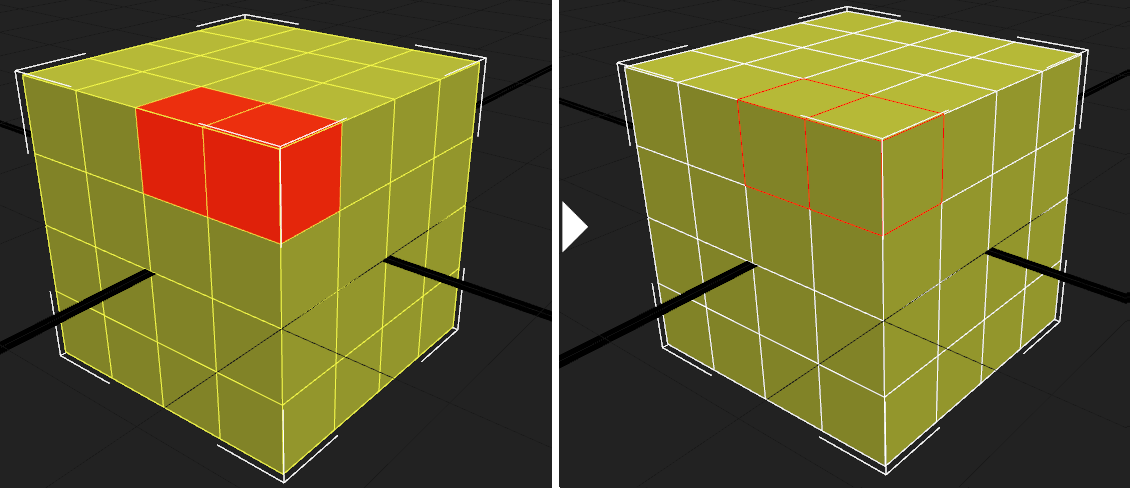
The Ignore Backfacing checkbox is an important option when going to select components. This controls whether we can select components that face away from the camera or not. This is useful in cases where we would like to select only visible components. By checking this option, we can drag a large selection over our object and all components facing away from the camera will be ignored.
We can convert our current selection of components to another by holding down either the Ctrl or Shift key and then clicking on the icon of the desired component mode we want to convert to. For example, we may have a few faces selected. Holding down Ctrl and switching to Edge mode will select all the edges associated with our faces.
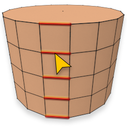
By selecting an edge and clicking on Ring Selection, all the edges on the other side of neighbor polygons will be selected as a ring.
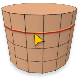
By selecting an edge and clicking on Loop Selection, all the edges that have the following criteria will be slected:
Each vertex must have at most 4 vertices to be part of loop selection, and the next edge should be a connected edge that has a shared edge in neighbor polygons or it is on border.
By selecting a face and clicking on Select Element, all the neighbor faces that are part of one separate mesh (not connected to other faces) will be selected in viewport.
We can view the number of selected components and the total number of existing components in the mesh at the top of Edit Component panel. This can be useful when it isn’t clear how many components are selected. For example, when welding, vertices can be quite close together and can be difficult to distinguish visually. This number will help ensure that the proper number is selected before and after welding.